 +91-022-43533700/99
Oil coolersHere to realize their full potential, they must be used together with turbulators produced by our Turbulator division. While the basic graphs given in the basic curves section will cover the airside performance of the Heat exchangers it is very important to look at what happens inside the tube. Here the heat transfer coefficient will depend on the following:
a) Oil viscosity. Selecting the correct turbulatorsDesignWe can assist with the design data for the turbulators we produce on a case by case basis depending on the application, type of turbulators requested and the fluids involved. Our regular customers are also provided data which they can use for doing their own design. We encourage you to visit our website www.allturbulators.com for a better understanding of turbulators one can download our turbulator catalogue from this site. We have copied an extract of the design section of the allturbulators site here for your reference. Key elements of good Turbulator design.While we stand ready, and prefer to help our customers with design, we have tried to present an overview by presenting some graphical data. To do this we have done the following: Chosen a 3/4" OD tube as it is very widely used. For this tube OD, we prepared the following data:
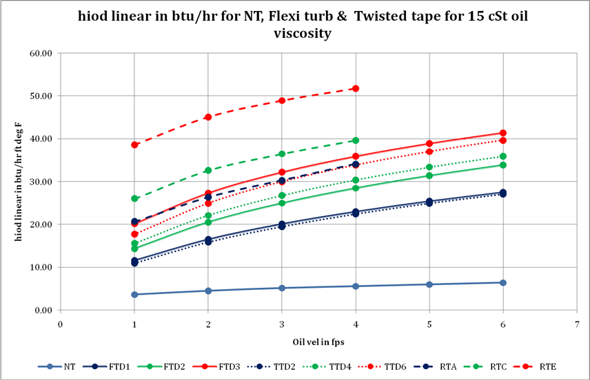
The pressure drop and heat transfer of oil of 3 viscosities, 5CST,
15 CST and 25 CST travelling through the tubes at a flow rate of
1 to 6 feet per second. This data was prepared for the following
Turbulator cases:
Since the possibilities here are infinite for the case of better comparing the two, we selected those twisted tape turbulators that gave with a 15 CST oil the same pressure drop at 3 FPS flow rate as the corresponding standard flexible turbulators. We must bear in mind though, that twisted tape turbulators thus selected have a very high twist ratio and are not commonly manufactured. However they were chosen for their value in comparision. Most commonly used twisted tape turbulators will have a lower performance and pressure drop. This data is represented graphically in the following charts/graphs.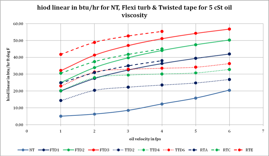
From the curves, we can arrive at the following observations: To get another angle on this performance we worked out the following table,where we have simply divided the heat transfer coefficient by the corresponding pressure drop to get the HTPD factor (Heat transfer coefficient per unit of pressure drop). We did this for the three oil viscosities for all the Turbulator models at all the studied flow rates. We have color coded the results so that it is easier to spot the best as well as the trend.
The following facts emerge: 1) Across all Turbulator types the HTPD factor goes down as the velocity Increases. 2) Across all turbulator types the HTPD factor goes down as the winding density increases. 3) Different Turbulator types give comparatively different results under different viscosity and flow conditions. 4) We can conclude that the best Turbulator is case specific. The following should be noticed: 1) The data for rigid turbulators are for rigid soldered Turbulators. If the same turbulators are not soldered they perform but not as well. This is due to the better contact and so better heat transfer due to soldering. 2) Just as pressure drop is a cost we pay for performance so is the cost of material and labour. The rigid soldered Turbulator while an extremely efficient turbulator is expensive to make and install. 3) Ease of cleaning and maintenance are also key factors in turbulator choice. 4) Since we make all types, we have nothing to loose in giving the correct advice. CustomizationTo a large degree we can customize our turbulators to meet your requirement.Research AssistanceFor customers wishing to experiment with new applications using turbulators, we are very happy to share our experience and provide support by way of small customized orders shipped by courier.Example 1 : Brine cooled Air cooler Here we have as case 1, wire wound fin tube (a special high performance fin tube we make) with no turbulators. In case 2 we have the same wire wound fin tube with internal flexible turbulators. This allows us to see the standalone effect of the turbulators. Number of rows drops from 20 to 12. Total tube length falls from 1164 to 636. This is a 45% decrease. Quite naturally the airside pressure drop falls with its commensurate power savings from 1.2 inches of water column to .8 inches. Even more remarkably the tube side pressure drop falls from .5 to .4 kgs per square cm. This demonstrates that though the pressure drop goes up nominally on account of turbulators the actual total pressure drop can actually fall as the number of passes reduce and the length of tube becomes less. Read MoreExample 2 : Produced Water heater. Here we have case 1 as a normal Helical fin tube with no Turbulator and 6 passes and Case 2 our own wire wound fin tube (a much higher efficiency fin tube we make) and our flexible Turbulator inside the tube. The results are given as under. The surface area of fins per linear foot of wire wound fin tube is 4.02 feet against 6.16 for the normal helical fin. The number of tube rows is reduced from 6 to 3 and tube passes from 6 to 1. Total fin surface area is reduced from 30,532 to 11,898. A reduction of 62%. Read More Example 3 : Shell and Tube exchanger (with Hot Oil on the tubeside and Produced water on the shell side.) Case 1 is without turbulators and case 2 is with flexible internal turbulators. The total length of tubes is reduced from 55 lengths of 16 ft to 60 lengths of 10 ft. This reduces the total length of tubes by 32%. Read MoreIn our study we have isolated the airside and tube side coefficient and dealt with how to enhance both to get the optimum result.
|
Concept EngineeringCurrently over 90% of our production is directly exported to USA, Mexico, UK, Austria, Germany, UAE, Singapore, Malaysia, Thailand, Indonesia, Australia. We are looking at developing meaningful partnerships all over the world. -Devang Jhaveri, President, Concept Engineering International.
Our Websites1) www.allturbulators.com 2) www.conceptengg.com 3) www.pinfintube.com Address: Second Floor, K.K. Chambers, Contact detailsPhone: 022-43533700/99 Email: mail@conceptengg.com |
||||||||||||||||||||||||||||||||||||||||||||||||||||||||||||||||||||||||||||||||||||||||||||||||||||||||||||||||||||||||||||||||||||||||||||||||||||||||||||||||||||||||||||||||||||||||||||||||||||||||||||||||||||||||||||||||||||||||||||||||||||||||||||||||||||||||||||||||||||||||||||||||||||||||||||||||||||||||||||||||||||||||||||||||
 |
|
Heat Transfer Specialists, Manufacturers of Turbulators, Wire Wound Fin tubes, Brass and Naval Brass plates |
Visit us at Stall C74 in the Thermal Processes Hall 6.1 at Achema, Frankfurt.
|